
Start with the joint components
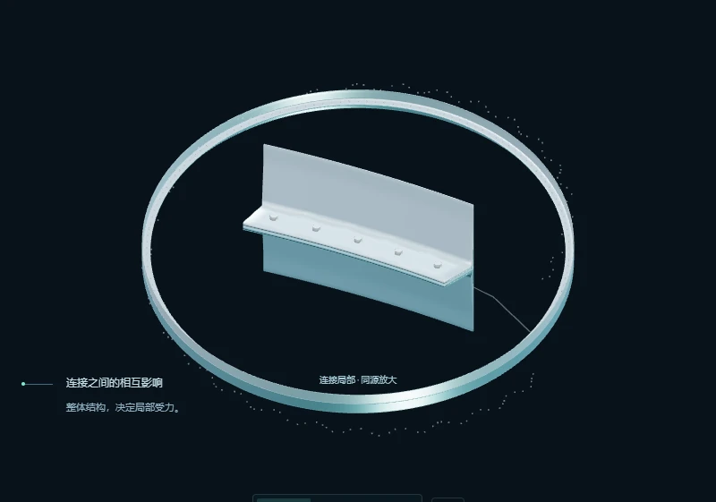
Parts, bolt groups, clamped layers and interfaces belong to the same project. Review local forces in the context of the full structure.
Structural relationship → Analysis modelNonlinear joint analysis · Engineering verification · AI design assistance
Use the load paths of the actual structure to inform design decisions.
Consider how one bolt interacts with the rest of the joint.
Use finite element results to understand the response and engineering criteria to assess it.
End-frame mesh · Animated markers indicate the loading direction
Actual structure Nonlinear response Traceable conclusions
downward explorationEccentricity, local stiffness, multiple contact interfaces and bolt groups all affect how load travels through a joint. Nexus organizes those effects into a process you can calculate and explain.
Keep the established
design verification principles
while investigating the actual mechanical response.
Finite element analysis shows how the structure carries load. Extract meaningful quantities from the field results, then assess strength, life and joint function against defined criteria.
View along a connectionFollow one joint through structural definition, assembly, response and engineering assessment. Each step provides evidence for the next.
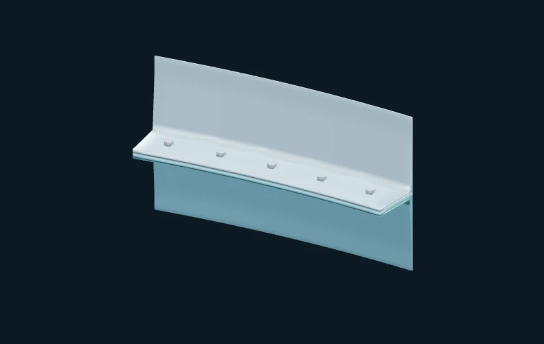
Local results come from the full model and retain their source as you change the viewing scale.
Parts, bolt groups, clamped layers and interfaces belong to the same project. Review local forces in the context of the full structure.
Structural relationship → Analysis modelPreload established, adjustment locked, then enter working load. Friction, contact opening and closing, and deformation collectively affect the subsequent response.
Preload → Lock → OperationDisplacement, stress, and interface state should be read together with operating condition and position. Field changes make load transfer gradually clear.
Saved field → Position and operating conditionClearly define sections, free bodies, coordinates, and reference states. Organize section forces, clamping forces, tangential loads, and support responses, connection solving and verification.
Field results → Engineering quantitiesLoad requirements, criteria basis, functional margin, and control areas should be placed together. Each conclusion can be traced back to its input and data.
Requirements and capacity → Solutions and reportsView the prototype reference state and working state saved in the end frame. Switch observation range and field variables, placing overall changes and local details in the same data set.

Abaqus/Standard 2020 saved results · automatic color scale for the current range · deformation scale affects the display only. Displacement uses original nodal values. Displayed stress is derived using the stated method.
Each result can be traced back to its sourceModel, analysis step, frame, entity, and processing aperture collectively define a cloud plot.
Complete C3D20 mesh and saved fields from the Flangeinner prototype of the end frame. A local view is composed of the five-bolt region of the original model.
Displacement magnitude is calculated from the original U vectors. The displayed von Mises stress is derived from integration-point values, then element averages, then averages across adjacent surface elements of the same part. Use the applicable VDI nominal stress or engineering criterion for compliance decisions.
This demonstration retains the numerical values and applicable ranges of the prototype stage, does not provide an engineering acceptance conclusion for full circle connections.
In group connections, load direction and eccentricity change the load sharing relationship. Use a normalized circular distribution model to understand why it is worth studying each connection.
Mechanism illustration · Normalized allocation relationship, not finite element results
The same overall requirement may be concentrated in different locations. Actual allocation also depends on structural stiffness, contact, and assembly status, requiring return to the complete analysis model.
AI understands the current connection, user constraints, and engineering evidence. Organization, calculation, comparison, and delivery ensure that research can continue, and each step is traceable.
Keep the bolt specification unchanged, compare the preload adjustment route and the local thickening route. Organize the need for verification of loading conditions, evaluation indicators, and design basis.
Select a Task Scenario, Observe How the Model, Research Path, and Deliverables Interact.
Identify the connected objects, target, and allowed changes.
Establishing benchmarks, candidate paths, and operating conditions.
Verify sources, organize comparisons, and identify items to be verified.
Organize research plan, basis, and next steps.
AI collaboration workflow example, demonstrating pre-set steps without calling AI services or executing solving.
Work around drawings, assembly, operating conditions, connected objects and existing results, clarify inputs and assumptions.
Organize schemes, schedule calculations, verify results within authorized scope, support pause and resume
Programming post-processing, specialized charts, experimental comparison, and interactive reports respond to specific research needs.
The real prototype connects modeling, assembly, solving, result viewing, engineering measurement, and VDI verification, laying the foundation for broader connection design.
2026-10-14 Real photo · Current prototype interface · Saved WORK displacement amplitude results
Start with a specific engineering problem,
precipitate reusable
engineering method
These records establish the engineering basis of the prototype. Whole-circle evaluation, preload coverage, and applicability to broader structures still require corresponding methods and verification.
Nexus aims to introduce the verification concept of bolted joints into a broader range of geometry, loading, and contact states. It supports more flexible modeling and retains sufficient basis for design judgment.
Around the connection object and real force transmission relationships, build the model, expand irregular bolt groups, multiple interfaces, and complex geometries.
Identify key bolts and interfaces based on load cases and verification items, study preload scatter, functional margin, and scheme feasibility range.
Parameter studies, sensitivity comparisons, preload and structural adjustments, materials and life methods, gradually form a reusable research process.
Use Axiom for analytical relationships, Forge for detailed local analysis, Sense for connecting to real measurement data, and Atlas for supporting knowledge and data. AI helps organize cross-phase research and interpretation.
TD Cadence Facing assembly process and preload implementation conditions,TD Sentinel Focusing on service observation and maintenance records. These records can provide reference for analyzing the operating conditions of connection groups and subsequent verification; cross-product data collaboration is still in planning.
collaboration direction of the kitEngineering problems, method verification, software development, and industrial cooperation.
Jointly advance the design and verification of complex fastened joints.